Provide GNSS corrections
The Orphéon network is made up of nearly 220 observation stations, spread over the entire territory of mainland France and the West Indies.
All of our stations form a large balanced RTK network that allows us to deliver centimetric GNSS corrections to our many customers to increase the accuracy of their precision GPS. Our various services are marketed in the form of subscriptions or hourly packages.
GNSS
GNSS stands for Geolocation and Navigation by a Satellite System. This term includes all the equipment and installations allowing positioning by satellites.
Generally by misuse of language, we used the generic term GPS for Global Positioning System to describe the various geopositioning equipment. However, this term is actually the name of a set of 24 American satellites placed in orbit at an altitude of 20,000 km.
This constellation of satellites, which was the first in history, therefore left its name to geopositioning technology.
Need to refine position
A standard GPS gives an approximate natural position with an accuracy of a few meters. This precision, which is sufficient for many consumer applications, can be corrected to obtain much better precision and make this technology usable by professionals for their precision work.
Corrections to gain precision
For its accuracy to be increased and usable in agricultural work, surveying, machine guidance or in many other fields of application (see) It requires corrections.
GPS will have to integrate additional data into their positioning calculations in order to correct the various errors related to this technology.
The correction data are obtained from fixed GPS (reference station) placed on positions whose coordinates are perfectly known. It is thus possible to quantify the various errors and to correct them in order to then be able to share them with other GPS located in the same conditions (nearby).
Precision GPS
We distinguish two types of GNSS receivers:
-
-
-
- Consumer receivers (Watches, telephones, tablets, cars etc…) which will work only in natural mode without the possibility of improving their precision thanks to corrections
- Precision receivers (RTK), which will be able to integrate external correction data allowing them to increase their precision.
-
-
Precision receivers have historically been developed for professional applications. Major manufacturers then offered increasingly integrated solutions adapted to each use where the precision of the receivers and the user interface are optimized to constantly improve productivity.
But today, the integration of precision GNSS chips is becoming more affordable by becoming affordable and making it easy to imagine all kinds of practical uses. It then becomes possible to integrate a centimetric precision RTK receiver in a compact, light and energy-efficient design to meet the requirements of these new applications and thus freeing imagination and creativity.
Go to fixes
To access the corrections, the precision GPS must have internet access. After identifying itself on the server and giving its initial position, the GPS will receive a data stream every second containing the correction parameters to be integrated into its positioning calculation. Within moments, the GPS will converge to centimeter accuracy.
For more than 15 years, the Orpheon network has offered real-time RTK Full GNSS precision increase GPS correction services allowing users, using a single GNSS sensor, to position themselves with centimeter precision in the national reference anywhere in France and in the West Indies.
On this page we will cover:
- The principle of corrections
- Sources of errors
- The “GPS” receiver
- NTRIP Client
- i-MAX, MAX, MAC, FKP, VRS fixes?
- The different formats for transmitting corrections
Different constellations of satellites- Waiters
- The advantages of the Orpheon network
- Full GNSS for what?
The principle of corrections of a GPS:
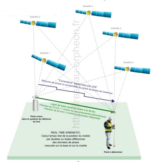
RTK
RTK (Real Time Kinematic) is a device for transmitting correction data from an observation base to mobile GPS in real time.
The mobile will then integrate this information into its positioning calculation to gain precision.
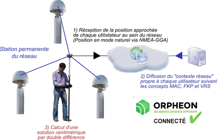
The NRTK (Network Real Time Kinematic) comes from the use of several bases of observations to optimize and model the information of corrections on the covered area.
The data from this network of observation stations is collected in real time on a centralized server. Mobiles connect to the server via mobile internet to get their corrections information.
Observation stations
Orphéon is the first French multi-constellation network in France.
With its 220 stations in mainland France, all Full GNSS: GPS, GLONASS, Galileo and BeiDou with a historical presence in the French West Indies.
The Orphéon satellite positioning correction system is based on a network of observation reference stations (OSR: Observation Space Representation) spread over the territory, each position of which is known with precision.
All the observations of this network are concentrated on a computing center to deliver to each user corrections allowing him to obtain a much more precise positioning.
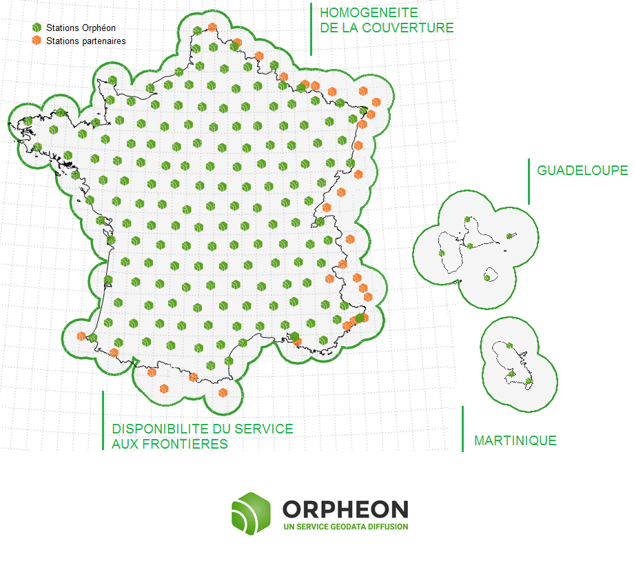
Click on the map to access the interactive network map
OSR services offer positioning accuracy to the nearest centimeter, within the network or within 30 km of the nearest reference station (in single station mode).
GNSS Positioning Accuracy Limits
The great distance traveled by the signal between the satellites and the receivers leads to a certain number of phenomena which influence the precision of GPS positioning.
The reception conditions at the level of the receivers also generate other phenomena. It is therefore the conjunction of all these factors that contributes to degrading precision.
Of all these sources of error, atmospheric refraction, responsible for ionospheric and tropospheric elongation, and orbital errors are the most problematic, as:
-
-
-
-
- they cannot be finely modeled beforehand (unlike electronic biases or antenna phase center variations),
- they cannot completely cancel each other out by multiple differentiations.
-
-
-
Sources of errors
Several natural errors affect the satellite/receiver distance measurement:
-
-
-
-
- The electronics bias of the satellite.
- The effect of satellite clock error.
- The position error of the satellite antenna phase center.
- The effect of satellite orbit error.
- Ionospheric elongation (refraction).
- Tropospheric elongation (refraction).
- Any multi-paths.
- The position error of the phase center of the mobile receiver antenna.
- The effect of receiver clock error.
- Receiver electronics bias.
-
-
-
The accuracy of GPS satellite orbits
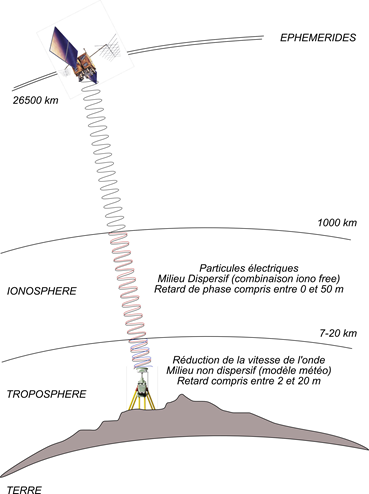
All the satellites used for positioning are constantly moving around the earth. Position parameters are updated weekly in the almanacs that are broadcast by the satellites and allow each GPS receiver to determine the trajectories and clock rates of the satellites it is using. Although their position is predicted in advance, their actual position is slightly different and this error will also naturally affect the position displayed by the receiver.
Refraction in the ionosphere
The signal from the satellites encounters a first zone that surrounds the earth at an altitude of almost 20 km: The ionosphere. The GPS signal must penetrate this layer on its path which causes a disturbance in the speed of the electromagnetic wave which propagates. The travel time taken by the GPS wave is thus modified by an unknown duration, called the ionospheric delay. The influence of the ionosphere is constantly changing due, for example, to solar activity.
As you can see on the SpaceWeatherLive.com website, this phenomenon is global with an ionospheric index K (quantification of geomagnetic disturbances). This is an average of the K indices relating to 13 stations located between 44 and 60◦ latitude; it is therefore an overall index.
The K index is a local index which characterizes the variation of the magnetic field at the station considered in relation to a calm reference day; these measurements are carried out using magnetometers.
The Kp index scale has 10 steps:
The levels of the Kp Index
refraction in the troposphere
The satellite signal encounters a second zone which is the lower layer of the atmosphere: the troposphere (from 0 to 10 km in altitude). The propagation time of the GPS wave is then affected by the water vapor content of this layer. In practice, weather conditions and tropospheric thicknesses differ depending on where you are. We note that the troposphere has a more specific influence on the vertical component of the position, the horizontal errors being more or less compensated by the fact that the satellites cover almost all directions on the horizon.
Multi-paths
At the level of signal reception conditions, there are phenomena which will further slightly lengthen the route of the GPS signal by reflection or rebounds of this signal on objects. The position thus obtained can thus be shifted but it is above all very unstable because as the satellites move, the angle of incidence on the reflector changes, and the position moves accordingly. The quality of the reception antenna is decisive here, some have shielding to attenuate these parasitic reflections.
Evaluation of these errors
The following table (Gerhard WUBBENA, 2008), specifies the result of these errors:
| Source d’erreur | Influence absolue |
| Orbites | Entre 2 et 50 mètres |
| Ionosphère | Entre 50cm et plus de 100 mètres |
| Troposphère | Entre 1 et 50 cm |
To go further technically
Precision GNSS receivers capable of accepting corrections will integrate components as well as additional software modules dedicated to precision calculations.
Principle of correction :
By placing a fixed GPS Reference Station (or base station) of which we know the exact and precise position in longitude, latitude and altitude, we can calculate the positioning error that a GPS returns to us at any time.
It then becomes easy to calculate the correction that gives us its exact position to the nearest centimeter (and sometimes better).
In use, we have found that it is possible to apply this same correction to other GPS units that are nearby (a few km – for information, the error is estimated at around 1 mm/km of distance). The fixedly positioned GPS is called a reference or pivot station.To distribute this correction to the GPS (in standard RTCM format) that are nearby, it is necessary to be able to communicate with them, either by radio or by internet via mobile telephony (modem).
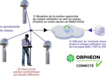
It is therefore important to note that the mobile (or rover) sends its position to the network calculation center (NMEA-GGA frame) then will calculate from the correction information received in return, its positioning solution by double differences, in order to eliminate uncorrelated errors in space, such as satellite clock error or their electronics bias.For more than 15 years, Géodata Diffusion has installed a network of 215 reference stations to cover the whole of France. All of the observations from each of these stations are collected on our servers, allowing us to then provide them to our customers via a subscription to our corrections for satellite positioning.The single Station mode :
By connecting a mobile GPS to a single reference station (or pivot) by radio or mobile telephony, it is possible to calculate and therefore take advantage of the corrections of the centimetric precision brought by the reference station to the mobile GPS.
The distance that separates the mobile GPS from the Reference Station becomes the baseline and the accuracy of the correction then becomes dependent on its length. The further away from the base station, the more the accuracy deteriorates. It is observed that within a radius of 30km the centimetric precision is preserved.
This mode allows a very fast start-up (reduced initialization time) and a moderate investment but remains fragile in the event of a stoppage of the base station and the need to secure this equipment.The network mode :
The network mode is an advanced mode for calculating corrections for positioning by satellites which implements several reference stations which surround a mobile receiver, thus creating a cell. By combining the individual corrections of each of the reference Stations of the cell, it is then possible to obtain a centimetric correction that is more homogeneous and more stable than with the single station.
This mode, which therefore does not depend on a single observation station, is of great interest because it then offers a correction which no longer depends on the length of the baseline. The quality of the corrections is homogeneous everywhere within the cell.
The network also offers an undeniable advantage because it does not depend on a single base station to generate quality corrections but on a cell in the event of a stoppage of one of the stations, the network continues to operate correctly and to deliver centimetric quality and precision corrections because it compensates for the absence of one of the bases.
The network allows a very fast start-up and a very short initialization time. Of course, the network mode represents a major investment because it requires a major infrastructure and great expertise that cannot be improvised.
Repeatability :
In some applications, it is essential to be able to return to exactly reposition oneself in the same place and sometimes after several years. This repeatability is obtained thanks to the centimetric precision of the corrections delivered on the one hand, but also by the precise and fixed positioning of the reference stations. Stability and control of their positioning is one of the keys.
Technically :
The operation of GNSS is based on measuring the propagation time of the signal transmitted by a satellite until it is measured by a receiver. The measurement of the propagation time of the signal coming from several satellites makes it possible by intersection to determine the position of the receiver.
The satellites therefore emit electromagnetic waves in the direction of the Earth which propagate at the speed of light.
The receiver on Earth measures the time taken by the wave to reach it. The receiver can then estimate the distance separating it from the satellite from the propagation time of the wave (approximately 70 ms). The precise measurement of this propagation time is essential since an error of 10 µs generates an error of 300 m: an accuracy of 1 ns is therefore needed to achieve a resolution of the order of one meter.
Accurate measurement of this propagation time requires perfect synchronization of the satellites with each other and with the receiver [Hofmann-Wellenhof et al., 2008 HOFMANN-WELLENHOF, B., LICHTENEGGER, H. and WASLE, E. (2008).Ó ]. This desynchronization occurring in the same way in all the measurements made in the direction of the satellites at a given time, it is therefore sufficient to estimate a desynchronization parameter (called clock error) to remove this uncertainty.
For standard positioning by GNSS, 4 unknowns must therefore be determined:
- Three position unknowns, in a geocentric frame, linked to a reference system specific to GNSS;
- A time unknown, linked to the desynchronization of the receiver with GNSS time.
Positioning methods
different positioning methods :
- Standard: Absolute positioning on real-time or delayed code; the precision is of the order of 5 m
- DGNSS: Differential GNSS, relative positioning on real-time or delayed code measurement; the precision is of the order of 50 cm.
- RTK: Real Time Kinematic, relative positioning on real-time phase measurement; the precision is of the order of 4 cm.
- Static: Relative positioning on real-time or delayed phase; the accuracy varies between a few millimeters and a few centimeters depending on the occupation time.
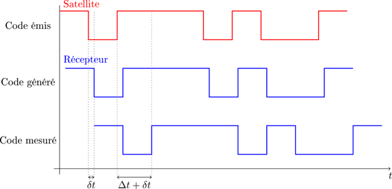
Code measurement
The receiver continuously receives the code from the satellite with a delay coming from the time taken by the wave to travel the distance between the satellite and the receiver. The receiver therefore measures this delay or shift, equal to the difference between the instant of reception (receiver clock) and the instant of transmission (transmitter clock). Since the receiver and transmitter (satellite) clocks are not synchronized, the time difference is marred by an error that must be estimated.
Mesure de Code
4 unknowns must therefore be determined: for instantaneous positioning, the measurement of at least 4 pseudo-distances is therefore necessary.
The receivers currently used make it possible to carry out the code measurement with an accuracy of the order of a hundredth of a cycle (length of a bit).
Phase measurement
Another technique than code measurement that can be used for positioning by GNSS is based on measuring the phase difference between the signals received and generated by the receiver. This measurement can be made on the different carriers used by the GNSS. Of course, the receiver and transmitter (satellite) clocks not being synchronized, the measured phase shift is tainted by a synchronization error which it is always necessary to estimate.
Mesure de Phase
The signal transmitted by the satellite is received by the receiver. an integer number of cycles, the period of the signal, the fractional part of the measured cycle.
However, only the fractional part of the propagation time of the signal between the satellite and the receiver counted in number of cycles can be measured by the receivers: the whole number of cycles elapsed since the start of the measurement is unknown: we speak of ambiguity of the phase measurement. The integer ambiguity is then defined as being the integer number of cycles elapsed at the start of the measurement.
During an observation session, care is therefore therefore taken not to interrupt the signal observed in the direction of a satellite. In the event of an interruption, it is called a cycle jump: the value of the entire ambiguity changes.
Note: For GPS the wavelengths associated with carriers L1 and L2 are respectively A1 = 19.0 cm and A2 = 24.4 cm. The precision on the phase measurement is therefore sub-millimeter.
Navigation Messages
In addition to being phase modulated using the code, GNSS signals are also modulated using the navigation message. The navigation message contains information that is used by the receiver, including:
- The position of the satellites (ephemeris) and information about it (satellite status).
- The elements making it possible to obtain the date of the emission of the signal, in the time scale of the satellite.
- The satellite clock correction to be applied to overcome its drift with respect to GNSS time.
- More general information: global parametric model of the ionosphere (for correcting its effect), almanac of all satellites (health, approximate position)..
RTK Definition (Wikipedia)
Real Time Kinematics (RTK) is a satellite positioning technique based on the use of measurements of the phase of the carrier waves of the signals emitted by the GPS, GLONASS or Galileo.nition RTK systems.
A reference station provides real-time corrections to achieve centimeter-level accuracy. In the particular case of GPS, the system is then called Carrier-Phase Enhancement or CPGPS.
- Differential phase processing of GNSS signals
- Centimetric precision inversely proportional to the “baseline” due to the spatial decorrelation of error sources and in particular atmospheric errors.
- Receive the approximate position of the user (NME-GGA) connected by TCP/IP (GPRS, EDGE, UMTS (3G) see xDSL or Internet by satellite)
- Model in real time the errors affecting the user’s site and send him “corrections” specially generated for his work area (MAC, VRS, FKP network concept)
- Disseminate corrections reliably and transparently by relying on existing Telecom networks
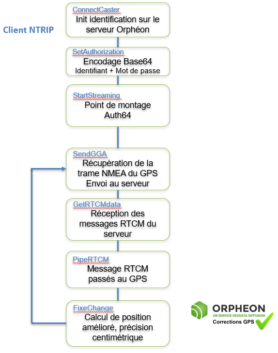
NTRIP Client
The NTRIP (Network Transport of RTCM data over IP) protocol is used to send RTK correction data from the base to the rover via the Internet.
This is especially useful in areas where traditional radios do not work well due to trees or hills.
The NTRIP client is part of the software integrated into the mobile. It obtains the correction data from the NTRIP Orpheon server and sends it internally in the GPS to the positioning calculation module. This program is a more useful alternative to GNSS internet radio.
Access to the Internet is generally via conventional means:
- A Wi-Fi connection
- A Bluetooth connection
- A mobile phone connection
As long as the GPS is not connected and does not receive RTCM correction messages from the Orpheon server, the GPS works like an ordinary GPS with an accuracy of several meters (natural mode).
To connect to the Orphéon NTRIP server, the mobile’s NTRIP client must be configured to identify itself to the server and obtain the corrections in the format adapted to its calculation mode.
- Server IP address (or DNS)
- The communications port
- User ID
- The user’s password
- The mounting point corresponding to the calculation mode
At the time of connection, the NTRIP Client will identify itself then it will send its current position to the server (frame $GxGGA) so that the server can define the reference stations that will be used in the correction solution (network mode) or the nearest reference station (single station mode).
The server will then send the correction message every second in the RTCM format selected by the mount point.
The GPS will integrate these correction parameters into its calculations to improve its precision which in a few cycles will reach the desired precision. The time taken to obtain this precision is the convergence time.
The GPS will also regularly send its position to the server in order to:
- to receive the best correction parameters (especially if the GPS is moving in a vehicle).
- to allow the server to determine that the mobile is still in the work area covered by the service.
- to allow the server to confirm that the connection with the mobile is still valid.
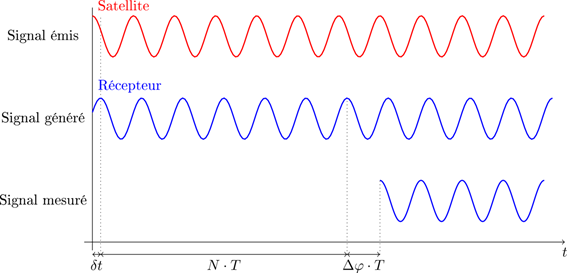
The different steps
Without going into the details of these programs, it is interesting to understand what is happening at each of these stages.
Correction message formats
The format and content of GPS correction messages are dictated by the standard of the RTCM organization. Each RTCM message consists of a variable number of 30-bit words, the first two of which serve as the header. In the context of real-time localization, messages 18 and 19 are of major interest, and the minimum quantity of information to be disseminated for an RTK correction is given by the formula:
(1) [bytes/s] = [30-bit words] x 5 = f x2 xFREQ x(3 + 2x N) x51
Where f denotes the rate of measurements; FREQ, equal to 1 or 2, describes the single or dual frequency nature of the receiver; N represents the number of satellites.The official version of the standard at the moment is called:
RTCM 10403.3, Differential GNSS (Global Navigation Satellite Systems) Services – Version 3 + Amendment 1 (April 28, 2020).See the complete list of RTCM messages and their usage: https://www.use-snip.com/kb/knowledge-base/rtcm-3-message-list/
version 3 groups messages together with associated data instead of sending separate messages to accomplish the same task. For example, in version 2, sending a complete RTK message required a message type of 18 for corrections and 19 for pseudo-range measurements, whereas in version 3 this information is grouped into a single type 1003. Multiple message types are defined for the same types of information to further improve efficiency; Type 1001 has GPS data only on the L1 frequency, while 1002 adds various additional information, while 1003 and 1004 do the same with L1 and L2 data for stations that can take advantage of the second carrier.
Version 3.x uses a variable-length message format and a single 24-bit cyclic redundancy check (CRC) over the entire message, as opposed to 6-bit parity for each 30-bit word. Like previous versions, the message format begins with an 8-bit extended preamble, followed by a 6-bit reserved area, and then a 10-bit message length that allows up to 1024 bytes of data. The message, each with its privately defined header and data, follows the header and is then limited by the CRC. The saving of data, especially in the case of RTK, is significant, an RTK version 3 correction set is generally half as long as version 2.
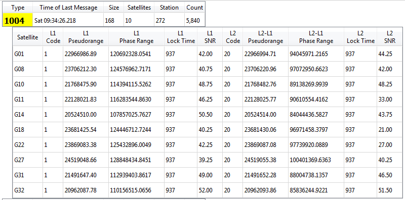
Example: RTCM 1004: Extended L1 and L2 GPS RTK Observables
This type of GPS message is the most common type of observation message, with L1/L2/SNR content. This is the most frequently found legacy message.
The mounting point
The mount point allows you to choose the type of data stream and the list of RTCM messages that will be exchanged between your hardware and our server, this corresponds both to the language that the hardware will use but also to the method of calculating the positioning that will be used.
i-MAX, MAX, MAC, FKP, VRS corrections ?
In the configuration of your equipment which will guide your choice of mounting point, the choice of the type of corrections will depend on your equipment, the measurements you are going to perform and the availability of services.
MAC
On the initiative of Leica Geosystelms and GEO++ in 2001, first NRTK standard for the correction of network messages which would make it possible to overcome the problems of the various existing approaches. Concept based on the notion of master and mobile (Master Auxiliary Concept) allowing the Mobile to receive raw observation data from the nearest Master station in order to perform its correction calculations.
MAX
This Leica Geosystems format is based on the principle of using a cell of several reference stations around the rover with a reference station (the closest). MAX corrections contain all of the cell’s correction information and provide the maximum level of accuracy and reliability for the rover.
These corrections optimize the bandwidth required to transmit the corrections.
FKP
The oldest FKP method, (Flächen-Korrektur-Parameter) developed by Geo++, consists of the principle of transmissions of a model of errors calculated for the place where the mobile is specifically located. Subsequently, the rover calculates the corrections itself in the same way as in VRS. In addition the correction of a physical reference station is used in combination with the FKPs to calculate the individualized corrections for the position of the mobile.
FKP corrections are transmitted in RTCM 2.3 format. This method, which provides the mobile with more information, is bandwidth-intensive and requires stable communication quality without being full GNSS compatible.
i-MAX
Introduced by Leica Geosystems RTK network corrections are based on the position of the rover are calculated from information relating to a virtual master station created by calculations in close proximity to the rover in order to reduce the length of the baseline and present a level of lower error. The position of the master station can change to follow the movements of the mobile.
Full GNSS compatible corrections transmitted in RTCM-3 MSM format
VRS
With the Virtual Reference Station, a concept introduced by Trimble, the rover interprets and uses network-correction data from a virtual base as if it were operating with a single physical base station on a very short baseline, this which dramatically increases RTK performance. However, it does not create a virtual vector.
The different formats for transmitting corrections
Format RTCM-2.x (DGPS)
This message is the most common way to send DGPS style code corrections for GPS or FKP
Format RTCM-3.1 ( RTK GPS Glonass)
RTCM versions 3.0 and 3.1 focus on optimizing bandwidth usage, higher integrity and management of RTK networks
Format RTCM-3.x MSM (RTK Full GNSS)
The RTCM-3 MSM standard thus ensures data interoperability with all compatible GNSS receivers by transmitting standardized observations of GPS + Glonass + Galileo + Beidou signals for all L1/L2 and L5 frequencies.
Message formats were previously limited to the L1 and L2 bands and to a single signal per band, which is why it has become necessary to use a new universal data format in real time: the MSM (for Multiple Signal Message) which is the new RTCM-3 key concept allowing all GNSS observation data to be presented in generic form.
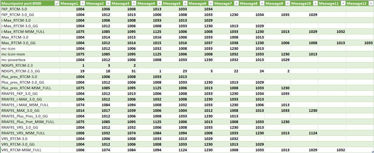
List of RTCM messages used
Here is the list of RTCM messages used for each mount point for port 8500 (all applications except agriculture. For agriculture see list of RTCM messages for port 7500).
Different constellations of satellites
Until today, we used the generic term GPS for Global Positioning System to describe the various geopositioning equipment.
However, this term is actually the name of a set of 24 American satellites placed in orbit at an altitude of 20,000 km. This constellation of satellites, which was the first in history, therefore left its name to geopositioning technology.

GPS + Glonass + Galiléo + Beidou
These satellites revolve around the earth and are therefore in constant motion. To establish a position, a minimum of 5 satellites is required.
Other constellations of satellites have thus been put into service by other countries:
-
-
-
-
-
- GPS for US satellites
- Glonass for Russia,
- Galileo for Europe has also been put into service, all are available in France.
- Beidou for China and more recently
-
-
-
-
All of these constellations are grouped together under the single name of GNSS for Global Navigation Satellite System.
GPS Satellites Active in 2019
-
-
-
-
- GPS: As of August 2019, 74 Global Positioning System navigation satellites had been launched, of which 31 were operational, 9 in reserve, 2 under test, 30 had been retired and 2 had been lost at the time. of the launch. The constellation requires at least 24 operational satellites and the number of official targets is 33.
- Galileo: has 30 satellites (24 operational and 6 in reserve). Galileo began offering early operational service on December 15, 2016, reaching full operational capability in 2019.
- Glonass: As of May 2019, 38 GLONASS navigation satellites had been launched, of which 26 had reached the correct orbit and 24 were currently operational.
- Beidou: BeiDou-3 third-generation BeiDou system will eventually include 35 satellites and is expected to provide global services when completed in 2020.
-
-
-
Hardware compatibility
Above all, the receiver must be able to receive and process corrections as an RTK client (which is currently not the case for the majority of smartphones). Different manufacturers, represented by our distributors, offer a wide range of receivers suitable for the various most common applications (see Areas of application). But it is also possible to find many electronic boards or components to integrate for the development of dedicated solutions or for the study and design of new applications.
Not all GNSS receivers are compatible with all satellite constellations available today. Thus the compatibility or the capacity of a receiver to process the signals coming from these different constellations of satellites makes it possible to increase the possibility of working in difficult zones where the masks are numerous because it is nevertheless always necessary a minimum of 4 satellites to establish a position.
The benefits of GNSS
By offering the possibility of mixing the signals of the different constellations of satellites, GNSS receivers make it possible to calculate a more stable position but also to work in more restricted places.
![]()
Indeed, buildings, trees, constructions, etc. create masks that prevent receivers from correctly receiving satellite signals. The more a receiver is able to process different signals, the less these masks will prevent you from working: hence increased working comfort and productivity.
Les Servers
Connect permanent GNSS stations in the network to a computing center
For more precision, these observation signals from the permanent antennas are grouped together on a server which will allow better signal processing and better determination and modeling of error sources by using:
-
-
-
-
- Predicted ultra-fast orbits with an inaccuracy of 5 cm corresponding to 3 ns instead of broadcast orbits which have a greater inaccuracy of 100 cm or 5 ns.
- Additional weather models, particularly tropospheric
- Geophysical models (tide and induced oceanic overload, solid tide, polar tide, atmospheric overload, etc.)
-
-
-
Signal processing
Regarding the position correction integrating all of these signals, it is necessary that the field equipment, but also the bases of the permanent stations of the network, are themselves compatible with all of these different satellites in order to be able to deliver a correction complete corresponding to the different users in the field.
As corrections are disseminated in real time, it is essential to have better infrastructures to guarantee all data flows:
-
-
-
-
- The streams from our stations to feed the servers
- The incoming and outgoing feeds of positions and corrections of each user
-
-
-
the user’s mobile must receive at each measurement epoch (typically every second) the “corrections” corresponding to its working area, even when it is moving.
These corrections reach each user continuously by GPRS with an average delivery time of 750 ms, the standard deviation, i.e. the deviation from the mean for 68% of the corrections sent, also being of this magnitude.
In order to keep the system consistent, there is therefore less than 250ms left for:
-
-
-
-
- Receive observations from permanent stations on the computer center
- Make them temporally consistent
- Compute “corrections”
- Send “corrections” to user
-
-
-
The advantages of the Orpheon network
-
-
-
-
-
- Compatible with GNSS RTK receivers of all brands
- Centimeter precision everywhere
- Very fast and simple commissioning everywhere
- Dense, regular and structured coverage of the entire territory
- High level quality and service
- Full GNSS: Increased productivity (Galileo corrections available since 12/10/2017)
- All you have to do is connect your GNSS receiver to the real-time corrections and accuracy increase service.
- You receive your positioning data very quickly, directly in the national repository.
- Network monitoring 24 hours a day, 365 days thanks to an international team
- Experienced technical support and assistance
- You can check the network status (via our smartphone app)
- Our offers are modular: Subscriptions or Packages
- A controlled investment
-
-
-
-
Reduce your investments with Orpheon
A single mobile GNSS receiver is enough: your initial investment is significantly reduced, and you have fine control over your budget depending on your activity.
The Orpheon services aim to simplify your access to corrections:
-
-
-
-
-
- No large initial investment in one or more base stations
- No installation monitoring (reference station, internet access, power supply)
- No maintenance / replacement of equipment to ensure
- No fear of failure or stoppage of the reference station, when a station stops, our mesh compensates and you continue to work with the same precision.
- No concept of distance with the reference station for constant centimeter precision, the Orpheon network calculates the optimal corrections from a cell of several stations
- No personnel to train or subcontractors to intervene to manage the reference station.
- No on-call to organize for sensitive applications or sites
-
-
-
-
We take care of all this for you and you can concentrate on your primary mission: your job.
Full GNSS for what ?
As a reminder, in order to be able to position itself within a few centimeters, a GPS/GNSS rover must be able to:
-
-
-
-
- perform noise-free phase measurements on at least 5 satellites well distributed in space,
- and receive differential corrections on these same 5 satellites
- increased positioning quality
- productivity gain
-
-
-
Adding the constellations of Glonass, Galileo and BeiDou satellites to those of the GPS constellation thus increases the possibility of receiving a sufficient number of signals of better quality.