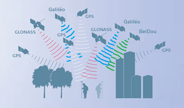
Masks and multipaths
In wooded areas or bordered by buildings, some satellites may be obscured and therefore unusable by the equipment on the ground to establish a correct position. It is also possible that these signals come from the reflections of a body of water, glass or metal surfaces, mountains, trees or constructions creating multipaths which alters the precision of the positioning.
Masks and multipaths
Positioning accuracy limits by GPS / GNSS methods
Several natural errors affect the satellite/receiver distance measurement:
- The electronics bias of the satellite.
- The effect of orbit error.
- The Effect of Satellite Clock Error.
- The satellite antenna phase center position error.
- Ionospheric elongation.
- Tropospheric elongation.
- Possible multi-paths.
- The position error of the phase center of the antenna of the mobile receiver.
- The Effect of Receiver Clock Error.
- Receiver Electronics Bias.
Of all these sources of error, atmospheric refraction, responsible for ionospheric and tropospheric elongation, and orbital errors are the most problematic, as:
- they cannot be finely modeled beforehand (unlike electronic biases or antenna phase center variations),
- they cannot completely cancel each other out by multiple differentiations.
The following table (Gerhard WUBBENA, 2008), specifies the result of these errors:
| Source d’erreur | Influence absolue |
| Orbites | Entre 2 et 50 mètres |
| Ionosphère | Entre 50cm et plus de 100 mètres |
| Troposphère | Entre 1 et 50 cm |
To determine the position, the GPS receiver calculates the distance at which the satellites are at the same time from the data of their ephemerides and based on its internal clock, knowing precisely the trajectory that the satellites follow, the receiver must theoretically use the same time as these satellites.
But due to the desynchronization of these clocks and disturbances in the propagation of the signals, this calculation loses precision (we speak of pseudo-distances).
- the signal is slowed down during its passage through the atmosphere (ionosphere and troposphere) in a variable manner.
- the signal can be reflected by elements on the ground (metal surfaces, glass, buildings, etc.) before being picked up by the receiver.
- the signal may be blocked and not reach the receiver (masks), in cities, due to trees, bridges, tunnels etc.
Errors affecting positioning accuracy by GPS / GNSS methods are related to:
- the geometry of the satellites used (PDOP),
- errors affecting the distance measurement between the various satellites seen and the user’s receiver.
To overcome the errors related to the good distribution of the satellites in the sky and to have the 5 well-distributed satellites necessary for an unambiguous calculation of the intersection of spheres, it is necessary to work:
- either in sufficiently clear environments,
- either with a sufficiently large number of satellites,
- so that the user’s mobile receiver can choose the 5 best usable satellites among the 13 to 14 satellites traditionally observable in France with a mask of 10° above the horizon.
Precautions
To limit the effects, certain precautions will make it possible to obtain better results such as moving away from these reflective surfaces or choosing equipment compatible with the different constellations but also with an antenna remote from the receiver and above all less sensitive to multipaths.
Unfortunately it is very difficult to decide on a given value because the impact of the disturbances will mainly depend on the exact place where you are.
- The disturbances fluctuate according to the zones and according to the times of the day
- In addition to the different disturbances, the impact can be different depending on the environment (buildings, trees, masks, multi-paths, number of satellites observed, etc.)
- The sensitivity of the hardware (its age, its software version, its calculation engine, the type of external antenna, etc.)
- The quality of the mobile internet connection (latencies etc.)
So, among the essential recommendations in times of disruption (and especially if your Z elevation measurements are important):
- Monitor GDOP remains below 3 – 4,
- Respect sufficiently long point acquisition times
- Revisit the important points at least once after at least 20 minutes (allows you to see any discrepancies)
But also we recommend in case of sensitive measurements:
- Save raw observation data in Rinex format in parallel with your real-time field measurements (then allows you to control with post-processing).
- Check a posteriori the different states of your mobile during the measurement session thanks to your Orpheon customer space and the recorded logs (allows you to see if the mobile has fixed the ambiguities, or if it is floating, etc.)
The purpose of these precautions is mainly to have a certain degree of confidence in the measurements taken and to be able to determine which ones would potentially be more doubtful.
The strategic choice of your equipment
Today more than ever, the choice of your equipment is essential.
If for years these physical disturbances remained quite discreet, they may have led us to believe that all the GPS receivers on the market were equal and that they presented more or less the same performance.
As we well know, there are sometimes false economies. It is sometimes better to acquire equipment from a major manufacturer with less functionality but to be sure of its performance in adversity and difficult conditions in the field.
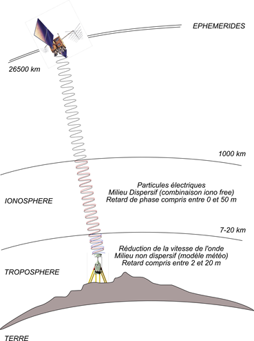
Error related to crossing the ionosphere
The main source of error affecting the precision of positioning by GNSS methods is linked to the atmospheric crossing of the signal and more particularly to the crossing of its ionized part called the ionosphere.
This ionospheric error is dispersive, insofar as it depends on the frequency of the signals used. The orbit errors and the tropospheric error being purely geometric.
Ionospheric error can be measured at any time at any station in the network through a so-called “Geometry Free” or “L4” frequency combination.
To finely model this ionospheric error over the entire network, it is important to have enough permanent stations to measure it (sampling points) before setting up mathematical models (interpolation) making it possible to determine, and therefore to correct for each epoch and each satellite (4D models), the errors affecting the position of each user.

Phenomena in the ionosphere
The ionosphere is a high layer of the atmosphere between about 50 and 1000 km altitude. In this atmospheric layer, the molecules are amputated by an electron under the effect of solar radiation (ranging from ultraviolet to X-rays) and form a plasma, that is to say a phase of matter made up of particles loaded with ions and electrons.
Depending on the electronic density of this plasma along the satellite/receiver line, the electromagnetic signal emitted by the satellites will be refracted to follow an optical path longer than the geometric path, this ionospheric elongation being able to reach 100 meters.
For the frequencies used in GNSS systems, the ionosphere is a dispersive medium since the refractive index n depends on the signal frequency.
From measurements on different frequencies, it is therefore possible to eliminate, or to estimate in real time, the value of the ionospheric elongation by carrying out different linear combinations of measurements (“Geometry free” or “L4” combination).
Ionospheric index I95
An ionospheric index, called Index I95, makes it possible to quantify the differential ionospheric activity between stations by giving the variation of the ionospheric error over a set of stations and a given time range. This index given in “parts per million” (ppm) can be perceived as giving the slope of difference in ionospheric delays between stations. It therefore reflects the probability that the ionospheric error at a given point is decorrelated from the interpolation model, the only way to reduce this probability being to bring the stations closer together, as illustrated below:

Parameters that vary ionospheric activity
The variation in ionospheric activity depends on the amount of radiation emitted by the sun. Solar activity being cyclical, with a wavelength of 11 years, as shown below with the last cycles and the detail of the last cycle:


The ionospheric activity also depends on the season and the solar time within a day, as illustrated below with the representation of the I95 index on the Orpheon network on March 3, 2012. It can be seen that the activity day is greatest between 10 a.m. and 2 p.m.

The I95 index threshold values are defined as follows:
- From 0 to 2 : no influence of ionospheric activity.
- From 2 to 4 : activity felt but without consequence.
- From 4 to 8 : activity felt and which may interfere with the measurement, first warning.
- Above 8: high activity and it is strongly advised not to work in these conditions.
The resultant of the geometric errors can be measured, always at any time on each station of the network, via a combination of frequencies called “Iono Free” or “L3”
Hence the interest of Multifrequencies L1/L2 and L5
Based on L1 and L5 frequencies emitted by satellites to make positioning more resistant to interference and signal reflections, especially in an urban environment. Concretely, the initialization time and the delay to fix or convergence are significantly reduced as well as the repositioning times in the event of disconnection. The use of multiple frequencies allows better rejection of repair signals, which makes it possible to process a maximum of direct signals, which provides greater precision and greater positioning repeatability.
Dilution of GDOP, HDOP accuracy…
The HDOP, a question of geometry
The positioning accuracy of a satellite navigation system (GPS) is affected by mathematical errors related to the geometry of observable satellites either because of their position and their distribution above the user. which can be defined as:

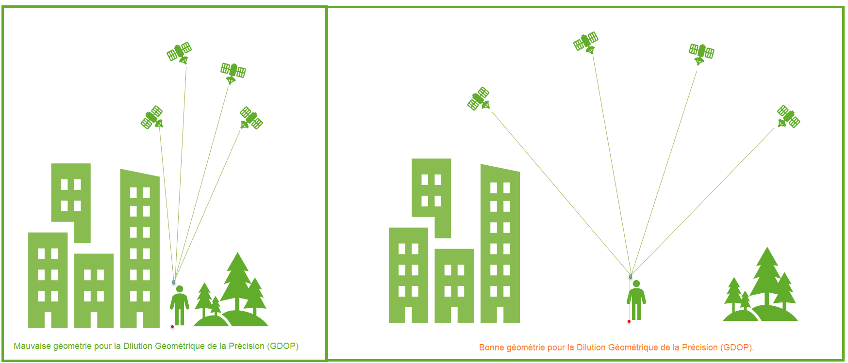
The idea of geometric DOP (GDOP) is to indicate how measurement errors will affect the final state estimate.
DOP can be expressed in a number of distinct measurements:
- HDOP – horizontal dilution of precision
- VDOP – vertical dilution of precision
- PDOP – position dilution (3D) of accuracy
- TDOP – temporal dilution of precision
- GDOP – geometric dilution of precision
Benchmarks
These values derive mathematically from the positions of the usable satellites. The signal receivers allow the display of these positions (skyplot) as well as the DOP values.
| Valeur DDP | Classement | La description |
|---|---|---|
| <1 | Idéal | Highest possible level of confidence to be used for applications requiring the highest possible accuracy at all times. |
| 1-2 | Excellent | At this level of confidence, position measurements are considered accurate enough to meet all but the most sensitive applications.. |
| 2-5 | Bien | Represents a level that marks the appropriate minimum for making accurate decisions. Position measurements could be used to make reliable navigation suggestions to the user. |
| 5-10 | Modérer | Position measurements could be used for calculations, but the quality of the correction could still be improved. A clearer view of the sky is recommended. |
| 10-20 | Équitable | Represents a low confidence level. Position measurements should be ignored or used only to indicate a very rough estimate of the current location. |
| >20 | Pauvre | At this level, measurements are inaccurate out to 300 meters with an accurate 6 meter device (50 DOP × 6 meters) and should be discarded. |
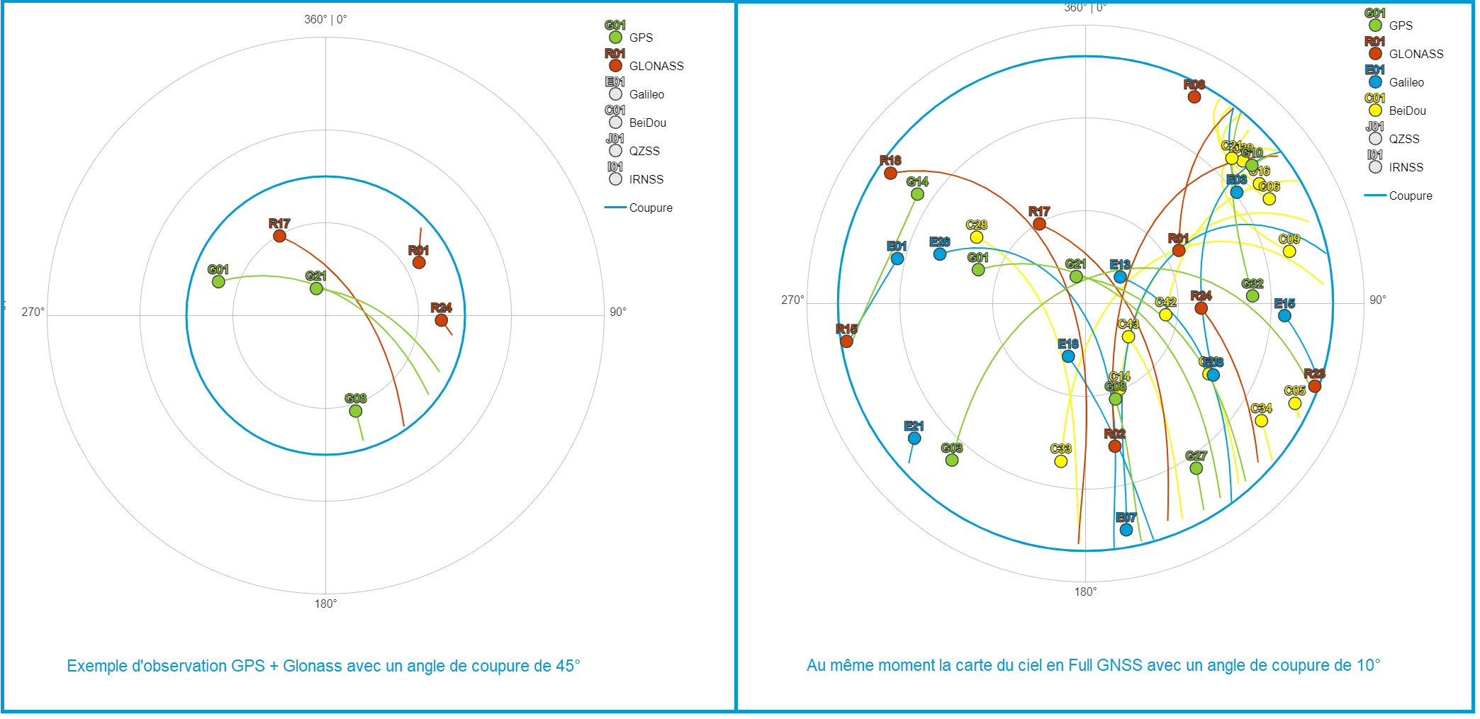
Sky map
The sky map allows you to get a good idea of the distribution of the satellites above you and therefore potentially of the DOP problems that you could encounter.
Example of observation of the sky of the GPS and Glonass constellations with a cut-off angle of 45° compared to the sky map in Full GNSS with a cut-off angle of 10°.